By Pritam Singh (QC Coating Inspector)
Surface profile (anchor pattern) is the “tooth” that helps coatings bond to steel. If the profile is too low, coating adhesion and durability suffer. If it’s too high, you risk pinholes, premature rusting at peaks, high paint consumption, and DFT nonconformance.
In this guide, I’ll explain how I measure surface profile in the field, compare the most common field methods, and share practical tips to avoid the mistakes that cause wrong readings.
What is Surface Profile?
Surface profile is the peak-to-valley height created by blasting or mechanical preparation. It is commonly reported in:
- µm (microns)
- mils (1 mil = 25.4 µm)
Most coating systems specify a target range, for example:
- 50–75 µm (2–3 mils) for many epoxy systems
- 75–125 µm (3–5 mils) for heavy-duty/high build systems
(Always follow your project specification / PDS.)
When to Measure (Timing Matters)
I measure profile at these stages:
- After blasting and before primer (main acceptance point)
- After stripe coat (if spec requires verifying profile isn’t filled/contaminated)
- After re-blast or touch-up areas (especially corners/repairs)
Important: Profile must be checked after dust removal and when the surface is clean and dry.
Field Methods Compared (What Works Best and When)
Below are the most common field methods and how I compare them in real projects.
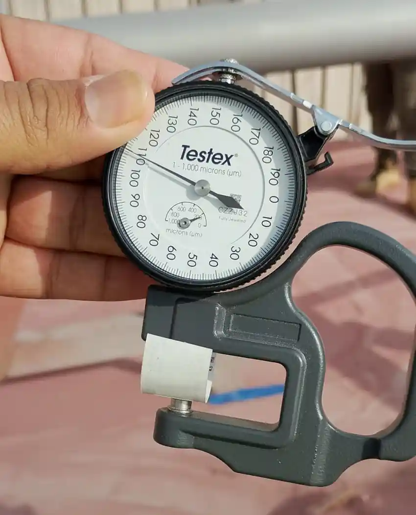
1) Replica Tape (Press-O-Film) Along Dail Micrometer — My most-used method
How it works: You burnish a foam tape onto the blasted surface, then measure thickness with a Dial micrometer. The foam compresses into valleys and gives a profile value.
Pros
- Very practical for field use
- Good repeatability when done correctly
- Works well on most blasted steel
Cons
- Sensitive to technique (burnishing pressure/time)
- Wrong tape grade selection gives wrong results
- Not ideal on very sharp/angular patterns without good technique
Best for: Routine blasting on carbon steel.
Accuracy tips I follow
- Use correct tape grade for expected profile range
- Burnish with consistent pressure (I use a firm, uniform motion; don’t “massage” lightly)
- Take readings on representative flat areas, not over weld spatter, pits, or edges
- Take multiple readings and average (details below)
2) Depth Micrometer / Dial Depth Gauge — Good, but surface contact matters
How it works: A base sits on peaks while a probe reaches into valleys.
Pros
- Direct reading method
- No consumables
Cons
- Can “bridge” over peaks or miss deepest valleys
- Base rocking and surface curvature create errors
- Needs stable positioning and clean surface
Best for: Flat areas where you can position the gauge correctly and repeatably.
Accuracy tips
- Ensure the base sits stable (no rocking)
- Avoid curved pipes unless you have suitable base/adapter
- Take more readings than usual (variation is higher)
3) Comparator (Visual/Tactile) — Fast screening, not my final acceptance
How it works: You compare the blasted surface by touch/visual to reference comparators (grit, shot, etc.).
Pros
- Very fast and simple
- Useful for quick checks and training blasters
Cons
- Subjective (depends on inspector experience)
- Not a numeric result unless combined with another method
Best for: Quick screening, confirming abrasive type/pattern, or supporting other measurements.
Complete Surface Preparation Inspection Checklist for Oil & Gas Projects
4) Stylus Profilometer (Portable) — Most detailed, not always practical
How it works: A stylus travels across the surface and creates a profile trace (Ra, Rz, etc.).
Pros
- High detail and data output
- Useful when spec demands roughness parameters beyond peak-valley
Cons
- Expensive and delicate for harsh field conditions
- Sensitive to dirt, vibration, curvature, and operator handling
- Results may not match “profile” values from tape/gauge directly (different parameters)
Best for: High-spec work, disputes, lab-like field setups, or when roughness parameters are specified.
Quick Comparison Table
| Method | Field Practicality | Repeatability | Cost | Best Use |
|---|---|---|---|---|
| Replica Tape with dial micrometer | High | High (with good technique) | Low–Medium | Routine acceptance on blasted steel |
| Depth Gauge / Micrometer | Medium | Medium | Medium | Flat surfaces, spot verification |
| Comparator | Very High | Low–Medium | Low | Quick screening / training / supporting evidence |
| Stylus Profilometer | Medium–Low | High (controlled conditions) | High | High-spec requirements, disputes, detailed reporting |
My Step-by-Step Process (Field-Proven)
Step 1: Confirm surface condition
- Surface is dry
- Dust removed (blow down/vacuum/brush as per spec)
- No obvious embedded abrasive, oil, or salts that can affect readings
Step 2: Select correct locations
I avoid:
- 25–50 mm from edges (unless spec requires edges)
- Weld spatter, pits, laminations
- Damaged areas from scaffold contact or grinding marks
I target:
- Representative zones (top/mid/bottom or north/south on pipe)
- Areas with similar blast angle and access
Step 3: Measure enough points (don’t under-sample)
A common and defensible approach in the field is:
- Minimum 3 locations per area
- At each location, take 3 readings
- Record average and note range (variation tells you blast consistency)
If the surface looks inconsistent, I increase the sampling.
Step 4: Record results clearly
My report always includes:
- Area/Item ID, date/time
- Method used (tape/gauge)
- Instrument ID + calibration status
- Readings + average + units (µm/mils)
- Acceptance criteria reference (spec clause / ITP)
Common Reasons Profile Readings Go Wrong (And How I Prevent Them)
1) Wrong tape grade / wrong expected range
Fix: Check spec target profile and choose the correct tape grade.
2) Inconsistent burnishing (replica tape)
Fix: Use consistent pressure, consistent time, and a repeatable motion.
3) Measuring over contamination (dust/salts/oil)
Fix: Ensure dust removal is completed and soluble salt testing is acceptable where required.
4) Mixing “roughness parameters” with “profile”
Stylus instruments may output Ra/Rz, which are not the same as peak-to-valley profile values used in many coating specs.
Fix: Confirm what the spec asks for (profile height vs roughness parameter).
5) Curved surfaces (pipes) causing gauge rocking
Fix: Use replica tape or proper adapters for curvature.
What If Profile Is Out of Range?
If profile is too low
Likely causes:
- Fine abrasive
- Low blast pressure
- Wrong nozzle size / worn nozzle
- Stand-off distance too far
Actions:
- Adjust abrasive grade
- Increase pressure/flow
- Replace nozzle
- Re-blast affected area
If profile is too high
Likely causes:
- Coarse abrasive
- Excessive pressure
- Wrong abrasive type (too aggressive)
Actions:
- Change abrasive grade/type
- Reduce blast pressure (within acceptable cleaning performance)
- Confirm coating system can tolerate higher profile (only if spec allows)
Internal & External Link Strategy (for your website article SEO)
Internal links (add 3–6)
- Soluble Salt Testing (Bresle Method) guide
- Surface Preparation Inspection Checklist
- Dust Test (ISO 8502-3)
- Blasting Parameters & Nozzle Inspection
- DFT Measurement & Common Mistakes
External links (add 2–4)
- ASTM D4417 (Field Measurement of Surface Profile of Blast Cleaned Steel)
- ISO 8503 series (Surface roughness characteristics of blast-cleaned steel)
- Optional: coating manufacturer PDS examples (for profile requirements)
FAQ
Replica tape is the most practical and repeatable method when used correctly.
I take at least 3 locations, and 3 readings per location, then record the average and range. Increase sampling if the blast looks inconsistent.
Comparators are excellent for quick checks, but final acceptance should be based on a measurable numeric method unless the spec allows otherwise.
Profilometers often output Ra/Rz roughness parameters, which are different from peak-to-valley “profile height” commonly specified for coatings.
No. Too high profile can cause pinholes, low DFT at peaks, higher paint consumption, and premature corrosion at high points.