Introduction
Accurate dry film thickness (DFT) measurement is essential for ensuring coating durability, corrosion protection, and specification compliance. While nondestructive gauges are widely used in the field, destructive testing provides unmatched clarity when individual coat thickness verification is required.
One of the most recognized destructive standards is ASTM D4138, titled Standard Test Methods for Measurement of Dry Film Thickness of Protective Coating Systems by Destructive Means.
This article provides a simplified, inspector-friendly explanation of the standard, its test methods, calculation techniques, reporting requirements, and field applications.
Overview of ASTM D4138
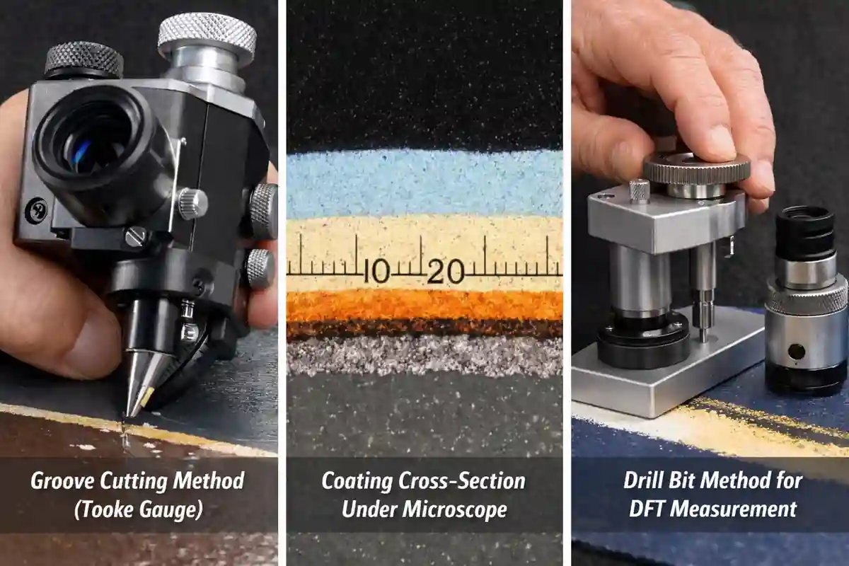
ASTM D4138 describes three destructive methods for measuring coating thickness by creating a precision cut through the coating and examining it under a microscope.
This standard is commonly used when thickness disputes occur. Over-thickness is one of the main reasons destructive testing becomes necessary in protective coating inspection.
Measurement Range:
- 0 to 50 mils (0 to 1.3 mm)
Suitable For:
- Flat surfaces
- Moderately curved surfaces
- Pipes as small as 1 inch (25 mm) diameter
Key Benefit:
Unlike magnetic gauges, this method is not restricted by substrate type.
Principle of Measurement
All three methods follow the same concept:
- A controlled angular cut or cavity is created in the coating.
- The exposed cross-section is observed using a 50× illuminated microscope.
- A reticle scale measures the slope distance.
- A conversion factor is applied.
- True coating thickness is calculated.
This allows measurement of:
- Total coating system thickness
- Individual coat thickness
- Layer interface verification
Test Method A – Groove Cutting (Tooke Gage Method)
Equipment:
- Tungsten carbide cutting tip
- Integrated 50× illuminated microscope
- Reticle scale
Tip Options & Conversion Factors
| Tip Ratio | Thickness Range | Conversion Factor |
|---|---|---|
| 1:1 | 20–50 mils | ×1.0 |
| 1:2 | 2–20 mils | ×0.5 |
| 1:10 | 0–3 mils | ×0.1 |
Procedure Summary:
- Mark test location.
- Place gage perpendicular to surface.
- Cut groove to substrate.
- Measure slope using reticle.
- Multiply reading by conversion factor.
Best Used For:
- Multilayer systems
- Verification of specific coat thickness
- Failure investigations
Test Method B – Grinding (Microgroover Method)
Equipment:
- High-speed rotary grinder (5000–10,000 rpm)
- Tungsten carbide grinding bit
- Positioning block
- 50× microscope
Angle Positions & Factors
| Position | Thickness Range | Conversion Factor |
|---|---|---|
| 1:1 | 20–50 mils | ×1.0 |
| 1:2 | 2–20 mils | ×0.5 |
| 1:4 | 0–3 mils | ×0.25 |
Procedure Summary:
- Grind partial cylindrical cavity.
- Ensure proper angle alignment.
- Measure reticle divisions.
- Apply conversion factor.
Advantages:
- Clear coat interface visibility
- Suitable for thick coatings
- Flexible angle selection
Test Method C – Drill Bit Method
Equipment:
- Cutter/drill body
- Handwheel (light/heavy)
- Precision drill bit
- 50× microscope
Calculation Formula:
- Thickness (mils) = Reticle divisions × 0.79
- Thickness (microns) = Reticle divisions × 20
Best Used For:
- Hard coatings
- Thick industrial systems
- Field verification
Significance of ASTM D4138
This standard is critical when:
- Substrate prevents magnetic gauge use
- Individual coat thickness must be verified
- Calibration disputes arise
- Failure analysis is required
- Contract compliance must be validated
While nondestructive standards such as ASTM D1186 and ASTM D1400 are widely used, destructive testing provides visual confirmation of coating layers.
Specimen Preparation Guidelines
To improve measurement accuracy:
- Use contrasting coat colors
- Ensure substrate rigidity
- Apply coatings uniformly
- Calibrate equipment using known thickness panels
- Avoid excessive pressure during cutting
Reporting Requirements
Inspection reports should include:
- Individual reading values
- Minimum, maximum, and average thickness
- Method used (A, B, or C)
- Test location
- Inspector name and date
- Any coating repairs performed
Precision & Limitations
- Lab-applied uniform coatings: ±10%
- Field-applied coatings may show variability due to:
- Surface roughness
- Application inconsistency
- Profile variations
Destructive testing requires localized coating repair after measurement.
Surface Profile Measurement Methods
Practical Application in Oil & Gas & Industrial Projects
For QC coating inspectors working in refineries, offshore platforms, power plants, and infrastructure projects, ASTM D4138 is especially useful for:
- EPC inspection validation
- Third-party audits
- Warranty claims
- Dispute resolution
- Critical corrosion protection systems
Given your experience in coating inspection within Oil & Gas environments, this method is particularly valuable for verifying multilayer epoxy and high-build protective systems.
Frequently Asked Questions (FAQ)
It provides visual confirmation and allows individual coat measurement, which nondestructive methods cannot do.
Yes, since the method is destructive.
Yes, unlike magnetic gauges, substrate type is not a limitation.
Method A with 1:10 tip or Method C for precise drilling.
Yes, but care must be taken to avoid damaging large areas.